finFET LAYOUT STRESS TEST CASES

Yotta has developed a whole family of finFET synthetic designs for the 14, 10 and 7 nm technology nodes. Customers can pick and choose the technology variants they think will be used.
There is considerable extra complexity in the finFET designs (multiple styles of finFET, 1-D layout, diffraction gratings with blockage or cut masks, local interconnect, and multi-port SRAMs).
Design rule variants in this family can have 1-D and 2-D routing on any subset of gate or routing layers (except metal 1), or diffraction gratings with blockage or cut masks on any subset of gate or routing layers. Contact Yotta Data Sciences for more information or to request a demonstration file using a particular variant.
Here are the variants in use with our current CPU and SRAM offerings:
- 7 nm - Cut masks or Blockage Masks + Diffraction Gratings + Fin Pitch Doubling
- 10 nm - Fin pitch doubling
- 14 nm - No variants
We've set up the design rules for the various technology nodes so that multiple synthetic design variants can be generated for each. In particular, we don't know if foundries will be using 1-D or 2-D layout for various mask levels, and we don't know if 1-D layouts will be generated directly, using diffraction gratings with blockage masks, or diffraction gratings with cut masks. All of the variant design rules for a given technology node are interchangeable, so we can switch a design from one variant to another without redoing the floor plan.
Our assumption, while developing the finFET technology, is that the figure of merit used by the engineers is no longer the gate length (a line width) but the "contacted gate pitch" - the distance from the left edge of one transistor gate to the left edge of the next transistor gate, over a diffusion contact. The transistor gate length is no longer scaling well due to current leakage. So, we've assumed that the foundries have switched to shrinking the spacing between gates and diffusion contacts to keep Moore's Law alive. Thus our designs and documentation focus on contacted gate pitch.
Wanting to be reasonably aggressive but not totally out of line, we've specified a 64 nm contacted gate pitch for the 14 nm finFET technology, a 48 nm contacted gate pitch for the 10 nm finFET technology, and a 40 nm contacted gate pitch for the 7 nm finFET technology.
Each design variant of a technology node and product type has its detailed documentation available before a purchase. Simply, by clicking one of the information request dialogues and send us your e-mail address. We'll be happy to send these details to you. Furthermore, of you're you'd like to sample our finFET designs, click on the sample design bar above and you will be given instructions on how to obtain about the sample designs and how to download our sample TCs.
Once we've established e-mail contact, we'll be able to answer any of your questions about our technology and your interests.

 | ||||
"The Company's technology established a common expectation amongst suppliers and customers regarding matters of OASIS compliance, performance and interoperability"
Naoya Hayashi
Electronic Device Laboratory
Dai Nippon Printing Co., Ltd

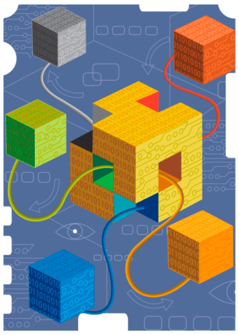

finFET Layout Stress Test Cases
10 nm
7 nm
14 nm
Each generation of semiconductor technology has enabled the realization of integrated circuits having far more functionality and complexity per square centimeter of silicon. Their realization has required advances in design and manufacturing automation / automation that can virtualize what a next generation integrated circuit may look like and how they'll behave; a developing capability that, decades long, has been defining the leading edge of software and hardware platform computational, memory and storage technology.
Without realistic design and manufacturing data that anticipates the functionality and the complexity of next generation integrated circuits, software and hardware developers have found it exceedingly difficult to produce automation they're confident will meet their customer's needs.
typedef struct _oasisReaderPath {
oasisUInt layer,dataType,halfWidth;
oasisInt startExt,endExt;
rawPointList *ptList;
oasisPropertyList *propList;
} oasisReaderPath;
Click . . . to go.
{0|1} = Cut Mask
{0|1} = Blockage Mask
{0|1} = Diffraction Grating
{0|1} = Fin Pitch Doubling
0 = Not a variant
1 = Variant
| = or
OAS = OASIS
GDS = GDSII
Workflow Auditor Point Tools
TM
®
© Getty Images
NEW at Yotta Data Sciences
* US Patents 9,122,825, 8,555,219, 8,266,571 and 7,685,545.
International Patents: China 200980129771.8, Japan 4768896, Korea 10-1580258, Israel 209907, European Patent 2310967.
OASIS® is a Registered Trademark of Thomas Grebinski
© 2008-2024 Yotta Data Sciences, Inc. All rights reserved.
February 16, 2024- Yotta is offering, to qualified partners, a six-month evaluation-period, with support, for its SEMI P39-0416 OASIS Reader/Writer Source Code.
Visit Page: OAS Reader/Writer
Visit Page: OAS Source Code